For Support, Service, Sales or other inquiries, call 1-800-705-2102
WHO WE ARE
Ashly designs and builds innovative audio systems for churches, restaurants, hotels, schools, courtrooms, health clubs, council chambers — any place that needs good sound.
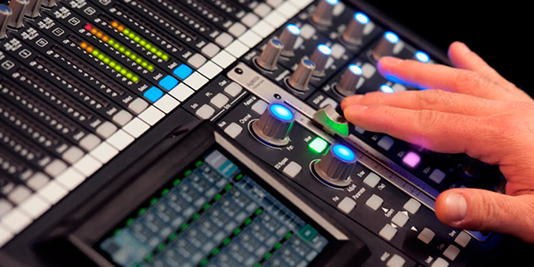
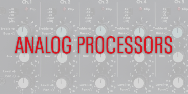
We meld easy-to-use control software, smart multi-mode DSP-laden power amplifiers, matrix processors, ingenious compact digital mixers and good old school analog signal processors into practical, affordable solutions. Established in Webster, NY; we’re going strong after 40+ great years.
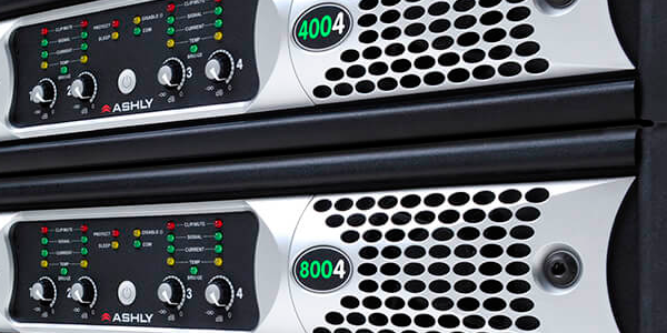
POWER AMPS FOR EVERY APP
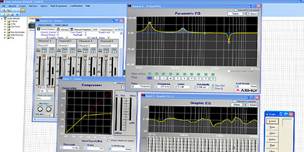
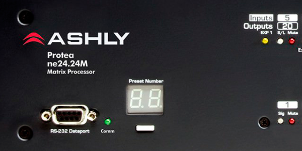
DSP FROM SEASONED EXPERTS

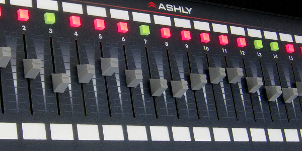
USER-FRIENDLY CONTROL SOFTWARE
WE SPEAK Dante® VERY FLUENTLY

OUR RELIABILITY IS LEGENDARY
MARKETS WE SERVE
Ashly’s sterling reputation for reliability and support have made us an integral part of virtually every level of sound installation. From live tours to bars and restaurants to multi-story corporate offices, we’re there even if you don’t see us.
Find out what our business partners and system integrators have known for over 40 years: customer love Ashly products for their bullet-proof durability, technical flexibility and most of all, sound quality. We’re committed to keeping your business profitable with value engineering that lasts for years and prevents costly call-backs.
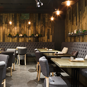
HOSPITALITY

EDUCATION

SPORTS

HOUSE OF WORSHIP